Back to selected workStructures · Team project

Structural calculations for a kite buggy

Our five person design team worked on a portable aluminum buggy with a 30 pound weight limit and a $400 parts budget. I shared the load, stress, and deflection calculations with two teammates.

Where
Wichita State University, ME 439
When
Spring 2015
My contribution
Shared structural calculations
Team model
CATIA work by Andy

The design our team analyzed
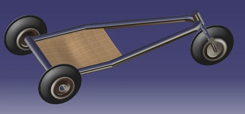
Team kite buggy model with a three wheel frame
Team CAD model created by Andy from the design dimensions. My contribution was shared structural analysis.Open larger ↗
29.7 lbEstimated design weight
$202.72Estimated parts cost
1.21Calculated drop case factor

Working from a load case

The analysis considered the rider and frame weight, bending, shear, deflection, and an assumed drop impact. We compared material and section choices against weight and cost, then carried the selected dimensions through the structural calculations.
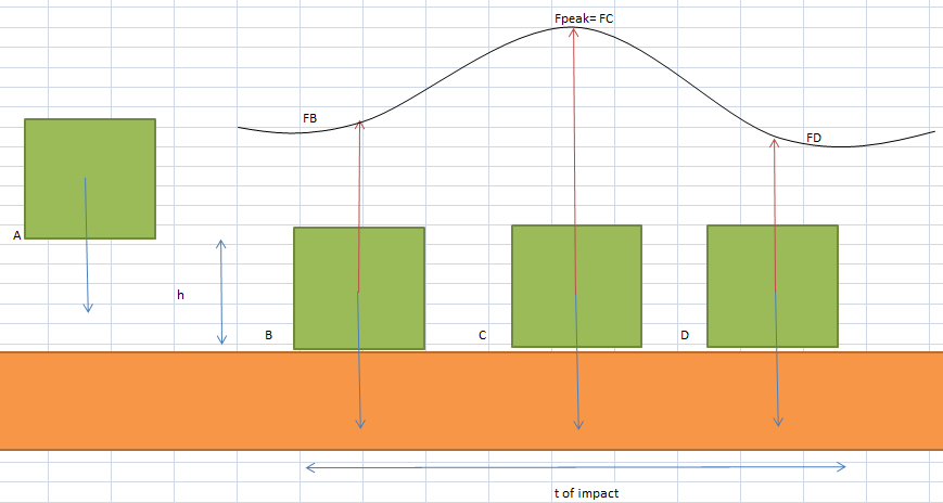
Drop impact assumptions and load diagram
Original impact model used in the team calculation.Open larger ↗
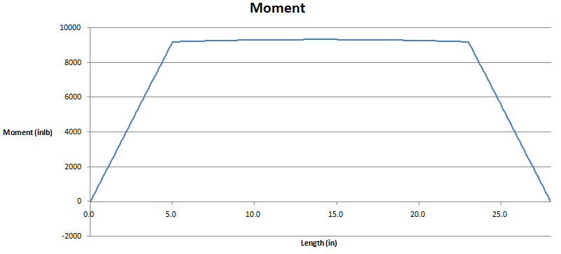
Rear axle bending moment plot
Original rear axle bending moment result.Open larger ↗

A result that called for another iteration

The calculated drop case factor was 1.21 against the project target of 1.25. The design met the estimated weight and cost limits, but that load case identified a structural requirement to revisit.

The supporting work
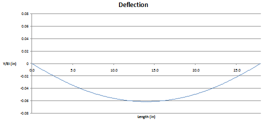
Calculated rear axle deflection
Original deflection calculation.Open larger ↗
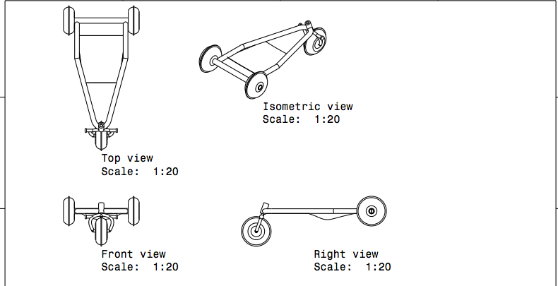
Team orthographic and isometric views of the buggy
Team design drawing. The project was an analytical design study.Open larger ↗
All projectsView resume